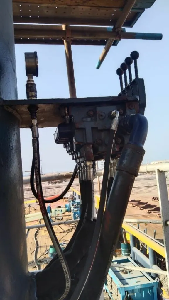
Almost every hydraulic machine, from a provision crane to a factory press, is the same four parts doing the same four jobs. A pump pushes oil. A relief valve stops the pressure going too high. A control valve sends the oil one way or the other. A cylinder or motor turns it back into movement. Play with the lever and the sliders above, then tick a fault and watch what changes.
How deep?
In simple terms
The pump makes flow, not pressure. An electric motor turns the pump, and every turn pushes out the same amount of oil. More flow means the cylinder moves faster.
The load makes the pressure. Oil only gets pushed as hard as it has to be to move what’s in the way. Lift a light load and the gauge reads low. Lift a heavy one and it reads high. Try it: change the load and watch the gauge, then change the pump flow and watch the speed. Each slider moves a different readout.
The relief valve is the safety limit. If the load needs more pressure than the relief valve allows, the valve opens and dumps the oil back to the tank. The machine stops moving, but nothing bursts. The cost is heat: all that oil is being forced through a small gap at full pressure, and that energy warms the oil. Hold the lever at the end of the stroke and watch the “heat” readout.
The control valve is the driver. Raise sends oil under the piston. Hold traps the oil in the cylinder so the load stays put, and lets the pump’s oil go straight back to the tank at low pressure. Lower sends oil above the piston and lets the oil underneath return to the tank.
The faults show two problems we see every week. A worn piston seal lets oil slip past inside the cylinder, so the load creeps down even with the valve in Hold. A worn pump leaks inside, so at high pressure it delivers less oil than it should and the machine gets slow and hot.
For engineers
The circuit is an open loop: the pump draws from a vented tank and the cylinder returns to it. The control valve is a 4/3 (four ports, three positions), spring-centred, with a tandem centre: in neutral P is connected to T, and A and B are blocked. That centre unloads a fixed-displacement pump at low pressure while holding the cylinder.
| Relationship | Formula | Example (100 mm bore, 56 mm rod) |
|---|---|---|
| Pressure to lift | p = F / A | 5 t → 49,050 N ÷ 7,854 mm² = 62.5 bar |
| Extend speed | v = Q / A | 30 L/min ÷ 78.5 cm² = 64 mm/s |
| Retract speed | v = Q / A(rod side) | 30 L/min ÷ 53.9 cm² = 93 mm/s |
| Return flow when retracting | Q(out) = Q(in) × A / A(rod side) | 30 × 1.46 = 44 L/min |
| Power lost over the relief | P = p × Q / 600 | 160 bar × 30 L/min / 600 = 8 kW |
Three points this circuit teaches that matter on real machines:
- Pressure is set by the load until something limits it. The relief valve, a stalled cylinder at the end of stroke, or a closed valve all push pressure up to the relief setting. Any time the pump’s flow can’t go anywhere useful, it goes over the relief as heat.
- The rod side has less area. Retracting is faster than extending for the same flow, and the oil leaving the full-bore side is more than the pump delivers. Return lines, filters and valves must be sized for that larger flow, not just the pump flow.
- Lowering a load is controlled by the outlet, not the inlet. The weight pushes oil out of the full-bore side. In this simple circuit the only thing slowing it is the valve’s own restriction. Real cranes and davits use a counterbalance valve, which is lesson 11.
To tell the two faults apart on site:
- Piston seal bypass: the load drifts in Hold, and in a bench test the cylinder drifts with its ports capped. Speed under load is slightly lower.
- Worn pump: speed falls as pressure rises, the case drain flow is high (on piston pumps), and the oil runs hot even when the machine isn’t working hard. A flow meter test at rated pressure confirms it.
Deep dive
Relief valve setting. The relief valve is set above the highest working pressure the machine needs (typically 10 to 15% above), and always below the rating of the weakest component: hoses, cylinder, pump. Setting it too low makes the machine stall under full load and run hot. Setting it too high removes the protection and lets pressure spikes damage hoses and seals. Set it with a calibrated gauge at the pump, with the cylinder at the end of its stroke, and lock it.
Heat balance. Every kilowatt that does no useful work becomes heat in the oil. Our 8 kW relief loss in a 100 L tank, with no cooler, would raise the oil temperature by about 3 °C a minute. In a UAE summer, with 45 °C air around the power pack, that quickly takes the oil past 70 °C, where it thins, leaks more and ages fast. That’s why operators holding the lever at the end of stroke, or a relief set too low, show up as overheating. See hydraulic overheating in UAE heat.
Valve centres. The tandem centre suits a single fixed pump and one function. A closed centre (all ports blocked) suits pressure-compensated pumps and accumulators. An open centre (all ports connected) lets the cylinder float. Lesson 9 lets you switch between them.
What this circuit is missing compared with a real machine:
- A suction strainer and a return filter, which keep the oil clean enough for the pump and valve clearances (lesson 15).
- A load-holding valve so the cylinder can’t drift through the control valve’s spool leakage (lessons 10 and 11).
- Pressure test points, a temperature gauge and a sight glass, so engineers can measure instead of guess.
Key numbers
| What | Typical value |
|---|---|
| Relief setting above maximum working pressure | 10 to 15% |
| Heat from oil over a relief valve | p × Q / 600 kW (bar, L/min) |
| Oil temperature to aim for | 40 to 60 °C |
| Rod-side to full-bore area, 100 / 56 mm cylinder | 0.69 |
| Pump unloading pressure through a tandem centre | about 3 to 10 bar |
Work out your own figures with the cylinder force and speed calculator.