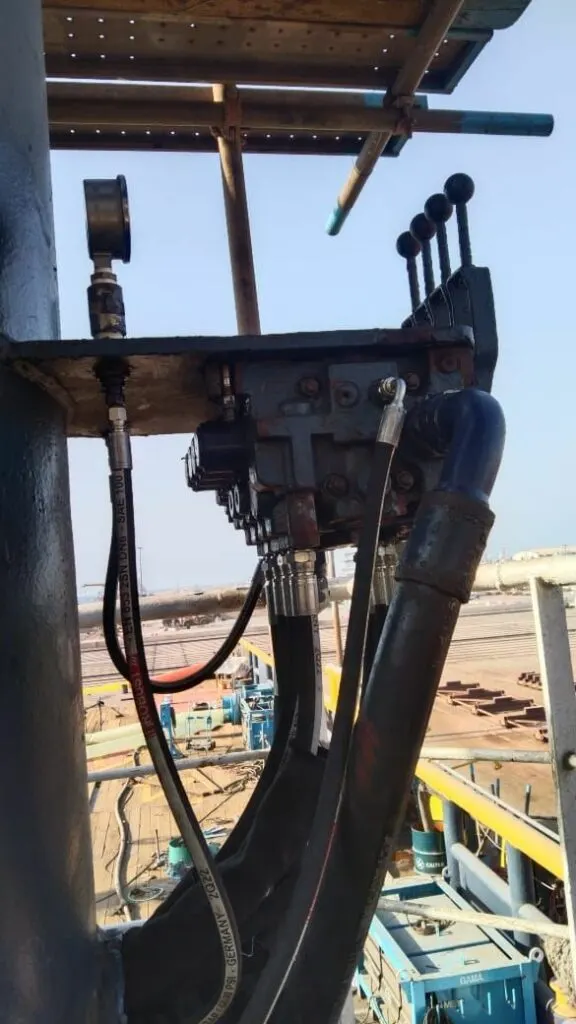
The directional control valve is the steering wheel of a hydraulic machine. On a crane it’s the bank of levers in the cab, on a winch the joystick on deck, on a press the solenoid valve on the power pack. Inside each section is a steel spool, ground to a few thousandths of a millimetre, sliding in a bore. Move the lever in the animation and watch how the spool’s lands open one path and close another, and how the symbol above changes with it.
In simple terms
The valve body has five grooves cut around its bore: one for the pump (P), two for the tank (T) and one each for the two sides of the cylinder (A and B). The spool has raised rings, called lands, that slide over those grooves and cover or uncover them.
Push the lever one way and the spool moves so that pump oil can reach one side of the cylinder while the other side drains to tank. Push it the other way and the paths swap. Let go, and springs push the spool back to the middle.
What happens in the middle is a design choice, and it is the most useful thing to understand about any valve:
- Closed centre: everything is blocked. The cylinder holds, but the pump’s oil has nowhere to go and dumps over the relief valve as heat, unless the pump can turn itself down.
- Tandem centre: the pump is connected to tank, the cylinder ports are blocked. The pump rests at low pressure and the cylinder holds. This is the common choice for a fixed pump.
- Open centre: everything is connected. The pump unloads and the cylinder is free to move. Good for a motor that should coast to a stop.
- Float centre: the pump is blocked, both cylinder ports go to tank. Used where a blade or a roller should follow the ground, and with pilot-operated checks and counterbalance valves, which need their pilot lines vented in neutral.
Try each with the load hanging on the cylinder.
The engineer's explanation, the deep dive, key numbers and the quiz open with a free account.
For engineers
Reading the symbol. The ISO 1219 symbol shows one box per spool position. The ports are drawn on the box that is in use at rest, usually the middle one, and the whole row of boxes slides under them when the valve shifts, exactly as in the animation. A 4/3 valve has four ports and three positions. Arrows show the flow paths; a “T” shape means a blocked port.
Spool and bore. Typical radial clearance between spool and bore is 5 to 15 µm. The lands overlap the grooves slightly in neutral (positive overlap) so the cylinder holds, which also creates a dead band before anything moves. Proportional and servo valves use zero or very small overlap and machined notches on the lands so flow increases smoothly with lever travel.
Leakage. A spool can never seal like a poppet. Oil leaks along the land clearance in laminar flow:
| Relationship | Formula | What it means |
|---|---|---|
| Leakage past a land | Q ∝ Δp × c³ ÷ (μ × L) | doubles the clearance c and leakage rises eight times |
| Effect of temperature | μ falls about 3% per °C near 50 °C | hot oil leaks much more |
| Cylinder creep | v = Q(leak) ÷ A | 0.5 L/min on a 80 mm bore is 1.7 mm/s |
That is why the animation lets you change the oil temperature: the same worn valve may hold acceptably in the morning and let the load sink by mid-afternoon. It is also why load-holding duties on cranes, davits and hatch covers are given to poppet-type check and counterbalance valves rather than the spool.
Metering. When the valve lowers an overrunning load, the load pushes oil out across the B to T metering edge, and the pressure drop there turns the load’s potential energy into heat. Without a counterbalance valve the speed depends on the load: heavier loads come down faster.
Deep dive
Sticking spools. The force available to move a spool is small: a centring spring of perhaps 100 to 200 N, or a solenoid of similar force. Silting (fine particles packing into the clearance while the valve sits still under pressure), varnish from overheated oil, a distorted body from over-tightened mounting bolts, and corrosion from water in the oil can all hold a spool. Symptoms: a lever that won’t return, a solenoid valve that works only after tapping it, or a function that keeps moving after the operator lets go. On a lifting appliance that is a runaway function, and the machine must be taken out of service.
Flow forces. Oil passing a metering edge at high velocity creates a force that tries to close the spool. At high flow and pressure drop this can exceed the solenoid’s force, which is why large valves are pilot operated: a small solenoid valve directs pilot oil to shift the main spool.
Sectional valve banks. Mobile cranes and deck machinery use banks of sections sharing a common P and T gallery. With open-centre sections in series, the first section has priority. Load-sensing banks (lesson 16) send the highest load pressure back to the pump so it delivers only the pressure needed.
What we check on overhaul. Spool-to-bore clearance and land edges (rounded edges increase leakage and dead band), centring springs, seals on the spool ends, solenoid coil resistance and plunger travel, and a bench leakage test at working pressure. A spool that is scored or a bore that is worn usually means a new section: spools and bodies are matched pairs.
UAE conditions. High ambient temperatures thin the oil and multiply leakage, and dust ingress through worn spool end seals scores the lands. Checking oil temperature and cleanliness is part of any creep complaint.
Key numbers
| What | Typical value |
|---|---|
| Spool-to-bore radial clearance | 5 to 15 µm |
| Spool travel, mobile valve section | 5 to 8 mm each way |
| Leakage of a healthy spool section | a few cm³/min at working pressure |
| Pump unloading pressure, tandem or open centre | about 3 to 10 bar |
| Centring spring force | about 100 to 200 N |