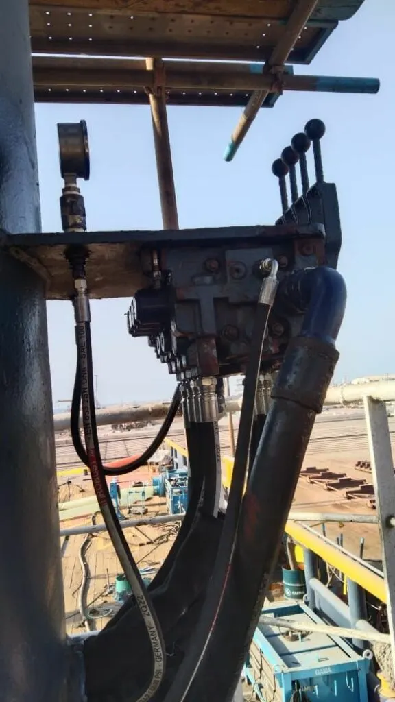
A crane boom wants to come down. Its weight, and the load on the hook, push oil out of the luffing cylinder all the time. Lift is easy: the pump pushes against the load. Lowering is the hard part, because now the load is doing the pushing, and without something to hold it back it falls faster than the pump can follow. The counterbalance valve is that something. In the animation, switch it off and lower the boom first. Then switch it back on.
In simple terms
Without the valve, opening the control valve to lower simply lets the oil out of the big side of the cylinder. The load pushes it out as fast as the pipes allow. The boom drops, and the pump, which is supposed to be filling the other side of the cylinder, can’t keep up. That side goes into a vacuum and the oil boils into bubbles. That’s cavitation, and it damages seals and makes the next movement jerky.
The counterbalance valve is mounted right on the cylinder, in the line from the big side. It is a spring-loaded valve set above the pressure the load makes, so it stays shut and holds the boom on its own. It has a pilot line from the other side of the cylinder. When you lower, the pump pressurises that side. That pressure, multiplied by the pilot ratio, adds to the load pressure and opens the valve, but only a little: just enough for the oil to leave as fast as the pump fills the other side. If the boom tries to go faster, the pressure on the pump side drops, the valve closes a little and slows it. The load comes down at the speed the operator asks for, whatever it weighs.
It does a second job too. Because it sits on the cylinder and holds the load by itself, a burst hose between the valve and the cab does not drop the boom.
The engineer's explanation, the deep dive, key numbers and the quiz open with a free account.
For engineers
The valve combines a free-flow check (for lifting) with a pilot-assisted relief in the return direction. It opens when the forces on its spool balance:
| Relationship | Formula | Default example |
|---|---|---|
| Opening condition | p(load) + R × p(pilot) ≥ setting | 133 + 3 × p(pilot) ≥ 280 |
| Pilot pressure needed | p(pilot) = (setting − p(load)) ÷ R | (280 − 133) ÷ 3 = 49 bar |
| Usual setting | 1.3 × the highest load-holding pressure | 1.3 × 214 bar ≈ 280 bar |
| Heat while lowering | P = p(cap) × Q(out) ÷ 600 | about 166 bar × 59 L/min ÷ 600 ≈ 16 kW |
Pilot ratio is the area ratio between the pilot piston and the spool’s seat, typically 3:1 to 10:1. A low ratio (2 or 3:1) needs more pilot pressure, so it wastes more energy as heat, but it is stable on long, flexible booms and large loads. A high ratio (8 or 10:1) opens with little pilot pressure, saves energy and suits stiff structures like winches, but small pressure changes swing the valve a long way, which makes long booms bounce. Raise the ratio slider to see it.
Setting. Set it high enough that the heaviest load can’t open the valve on its own (including dynamic loads and thermal pressure), and below the rating of the cylinder and valve. Lifting is unaffected: the oil goes in through the valve’s built-in check.
Control valve centre. In neutral the pilot line must vent to tank, so the control valve section for a counterbalanced function normally has a float or “motor” spool (A and B to T). The animation changes the centre symbol when you fit the valve.
Deep dive
Why the weak spring is dangerous. If the spring setting falls below the pressure the load makes, the load alone opens the valve. The boom creeps or drops even in Hold, and lowering is uncontrolled. Springs weaken with heat and age, adjusters get backed off by someone chasing slow lowering, and cartridges get swapped for ones with a lower range. On every crane service we check the setting against the plate value, with a calibrated gauge, not by feel.
Dirt and drift. A counterbalance valve is a poppet or a spool with a poppet seat, and like any seat it can be held open by a particle or eroded by flow. A boom that settles in Hold, measured at the hook or with a dial gauge on the cylinder rod, points to the valve or the piston seal. With the boom supported, capping the cylinder and testing each separately tells you which. Surveyors check drift during load tests, so a drifting boom fails the test.
Seized valves. Varnish, corrosion or a bent spool can lock the valve shut. The boom then won’t lower at all: the pilot pressure rises to the relief setting with nothing happening. The temptation on site is to crack a fitting to let the oil out. Don’t: it releases the load without control. Support the load mechanically, then remove the cartridge.
Bouncing and instability. The pilot pressure depends on the flow into the rod side, and the opening depends on the pilot pressure, so the valve and the boom form a feedback loop. Long booms flex, oil compresses and hoses swell, so there’s a delay in that loop. Too high a pilot ratio, too little damping, or air in the oil, and the loop oscillates. The cures are a lower ratio, a valve with a damping orifice in the pilot, or a restrictor that slows the pilot signal. On deck cranes and offshore cranes with long booms, 3:1 is common for this reason.
UAE conditions. Booms parked in the sun warm the trapped oil. Counterbalance valves usually include enough relief function to protect the cylinder from that thermal pressure, which is one more reason not to set them above the cylinder’s rating.
Key numbers
| What | Typical value |
|---|---|
| Counterbalance setting | about 1.3 × maximum load-holding pressure |
| Pilot ratio, cranes and long booms | 3 : 1 to 4.5 : 1 |
| Pilot ratio, winches and stiff structures | 8 : 1 to 10 : 1 |
| Pilot pressure to lower, default example | about 50 bar |
| Mounting | on or directly at the cylinder port |