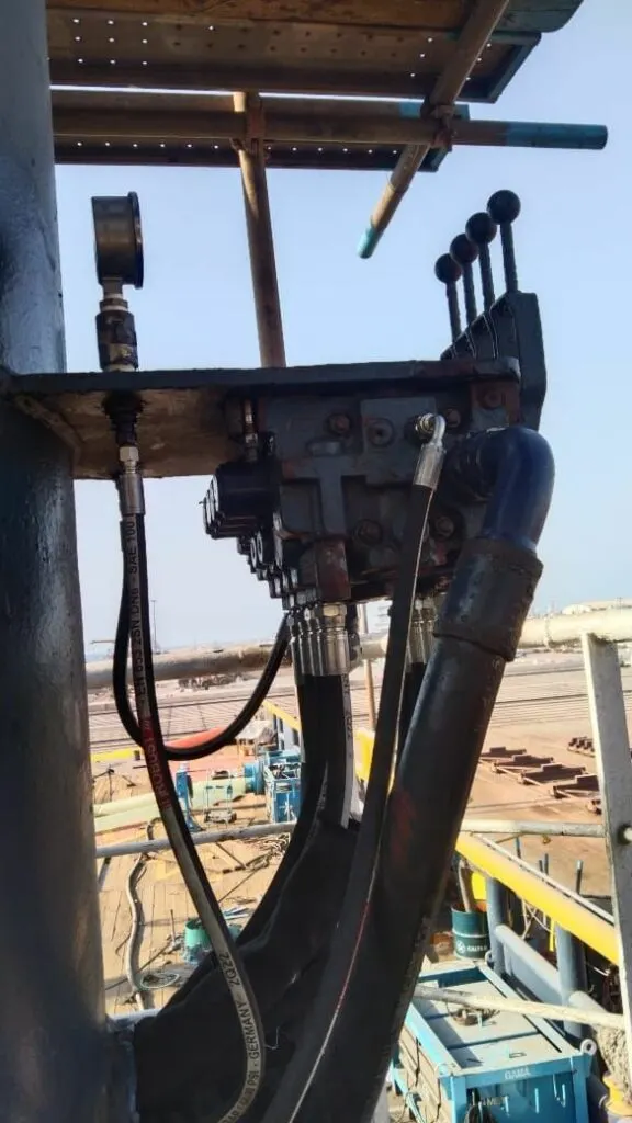
A ship’s provision crane brings together almost everything in the earlier lessons: a pump and relief valve, directional valves, a cylinder held by a counterbalance valve, a winch motor with a brake, and a filter keeping the oil clean. In the animation, move two or three levers at once and watch where the oil goes. Then load the hook past its safe working load, and try the faults.
In simple terms
A deck crane has three movements. Slewing turns the whole crane round on its pedestal. Luffing raises and lowers the boom. Hoisting winds the wire in or out to lift and lower the hook. Each one has its own section in the valve bank, worked by its own lever.
All three are fed by one pump. That is fine when only one lever is moved: that movement gets all the oil it can use. When two are moved together, the oil does what water does: it takes the easiest path. The movement that needs the least pressure gets its oil first, and the harder one waits. In the animation, hoist and luff together with a few tonnes on the hook: one of them slows down or stops. Operators know this as “the crane won’t hoist while I slew”.
The heavier the load and the further out the boom, the more pressure luffing needs. If it needs more than the relief valve allows, the boom simply won’t go up. That’s not a safe overload system (modern cranes have proper load limiters), but it shows why a crane that has “lost power” usually has a pressure problem.
Two things hold the load when the levers are in the middle. A counterbalance valve on the luff cylinder traps the oil under the piston, so the boom can’t fall. A spring-applied brake on the winch holds the hook, and only releases when oil pressure pushes it off. If either leaks or slips, the boom or the load creeps down.
The engineer's explanation, the deep dive, key numbers and the quiz open with a free account.
For engineers
The circuit in the animation is a fixed pump with an open-centre, parallel valve bank: in neutral the pump unloads through the open centre at a few bar; with a spool shifted, the centre closes and the pump’s flow goes to the work ports.
Pressures from the load:
| Function | Formula | 3 t on the hook, boom at 40° |
|---|---|---|
| Luff (boom moment) | M = (m(boom) × L/2 + m(load) × L) × g × cos β | (1.2 × 5 + 3 × 10) t·m × 9.81 × 0.77 = 271 kNm |
| Luff cylinder force | F = M / a (lever arm 1.4 m) | 193 kN |
| Luff pressure | p = F / A (160 mm bore) | 96 bar |
| Hoist motor torque | T = m × g × r / (i × η) | 3.15 t × 9.81 × 0.2 / (20 × 0.9) = 343 Nm |
| Hoist pressure | p = T × 20π / V (250 cm³/rev) | 86 bar |
| Hoist line speed | v = Q / V / i × 2πr | 80 L/min → 0.34 m/s |
Flow sharing in a parallel circuit. With two spools open, both work ports see the same pump pressure. The function with the lower load pressure takes flow first, limited only by its spool opening. The pump pressure settles at the load pressure of the function being fed, and the higher-pressure function gets nothing until the first one finishes or its spool restricts it. Skilled operators “feather” the levers to share the oil. Load-sensing valves with pressure compensators (lesson 16) do this automatically by holding the same pressure drop across each spool.
Where the heat comes from. In this circuit there are three sources, all shown in the heat readout:
- Throttling: when the pump runs at the higher function’s pressure, the lower-pressure function’s oil is throttled across its spool. Power lost = (p(pump) − p(function)) × Q / 600.
- Relief: with a spool fully open but the function unable to take all the pump’s flow (a small slew motor fed by a big pump), the rest goes over the relief valve at full pressure.
- Lowering: when the boom or the hook comes down, the load drives the oil out through the counterbalance or brake valve, and its potential energy becomes heat.
Lowering loads safely. Luffing down is an overrunning load. The pump feeds the rod side, and the pressure there pilots the counterbalance valve open against the trapped load pressure, so the boom comes down at the speed the pump allows and can’t run away. The hoist does the same with a brake valve and the brake release line.
Deep dive
Counterbalance valve settings. A counterbalance valve is set at about 1.3 times the highest load-holding pressure, and its pilot ratio (often 3:1 to 8:1 on cranes) decides how much rod-side pressure opens it. A low ratio gives stable, smooth lowering but uses more pump pressure; a high ratio is efficient but can make the boom bounce. A counterbalance valve passing oil across its seat lets the boom sink in neutral. The test is simple: boom out with a load, lever in neutral, mark the rod and time the drift, then isolate the valve from the cylinder to see whether it is the valve or the piston seal. See cylinder drift and lesson 11.
Winch brakes. Hoist brakes are spring-applied and hydraulically released. The brake release is fed from the hoist pressure line through a shuttle or a small valve, so the brake only lifts once there is pressure to hold the load. A brake that slips usually has worn or contaminated linings, often from a leaking motor shaft seal soaking them in oil, or a release line that doesn’t vent fully. Any slipping brake takes the crane out of service until it is fixed and tested.
Worn hoist motor. Internal leakage in the motor rises with pressure, so a worn hoist motor is slow with heavy loads and fine with light ones. With piston motors, high case drain flow confirms it. The leak flow at full pressure becomes heat in the oil and in the motor’s casing.
Return filters and bypass. A return filter has a bypass check valve, typically at 1.5 to 3.5 bar, so a blocked element doesn’t burst. Once the bypass opens, dirty oil goes straight back to the tank and on to the pump and valves. A clogging indicator on the filter head is the only warning. In the UAE, dust ingress through tank breathers and cylinder rod wipers loads filters quickly, so check indicators at every service.
After the repair, the load test. Any repair to the load path (luff cylinder, counterbalance valve, winch, brake, wire) is followed by a proof load test, normally 25% over the safe working load for cranes up to 20 t, witnessed by a class surveyor where required. The test checks the hydraulics hold under load as much as it checks the structure. Our crane load test guide covers how to prepare.
Key numbers
| What | Typical value |
|---|---|
| Provision crane working pressure | 150 to 250 bar |
| Counterbalance valve setting | about 1.3 × the highest load-holding pressure |
| Counterbalance pilot ratio on cranes | 3:1 to 8:1 |
| Return filter bypass setting | 1.5 to 3.5 bar |
| Proof load, cranes up to 20 t SWL | SWL + 25% |
| Heat from oil over a relief valve | p × Q / 600 kW (bar, L/min) |
Work out your own figures with the pump flow, power and torque calculator.